
Hi all,
I have just aquired a 1996 EJ20 SOHC Impreza motor for a conversion into a 83' coupe. I am after the ecu wiring diagram for this motor. 3 plugs into the ecu. The sticky post here is for a 4 plug ecu.
Thanks regards Darryl
1996 EJ20 SOHC N/A Impreza 3 plug ECU Wiring
Still trying to track down an ecu diagram for 96 Impreza manual GX EJ20. I am in need of the location of the wires for the:
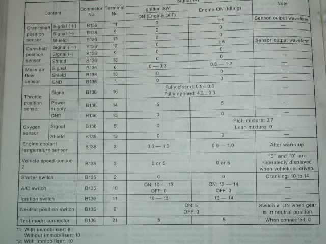
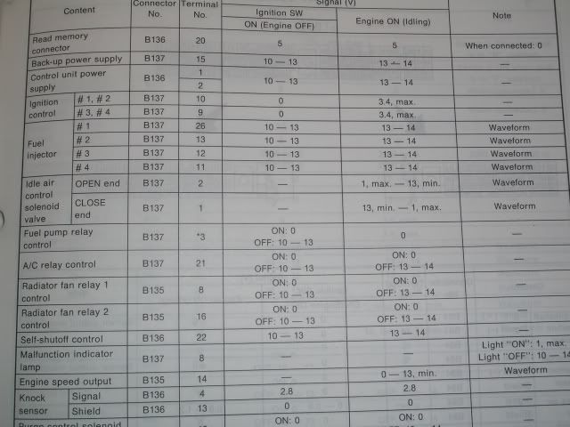
1. Vehicle speed sensor, Check engine light, tacho, cooling fan
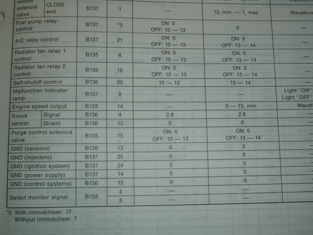
2. Power and earth wires in the ecu loom
3. Any for the abs / or cruise control.
As this is only a 3 plug ecu all the diagrams that I have come across are the the 4 plug ecu. Any help with this would be greatly appreciated.
Regards
1. Vehicle speed sensor, Check engine light, tacho, cooling fan
2. Power and earth wires in the ecu loom
3. Any for the abs / or cruise control.
As this is only a 3 plug ecu all the diagrams that I have come across are the the 4 plug ecu. Any help with this would be greatly appreciated.
Regards
There are half a dozen 3 plug ecu's as well so you need to have specific model type to get the right diagram. And yes, they all look the same and have completely different pinouts. I have had to just trace the wiring on some Gen 2 cars I have converted for this reason. The reason for changing them is still a mystery to me.
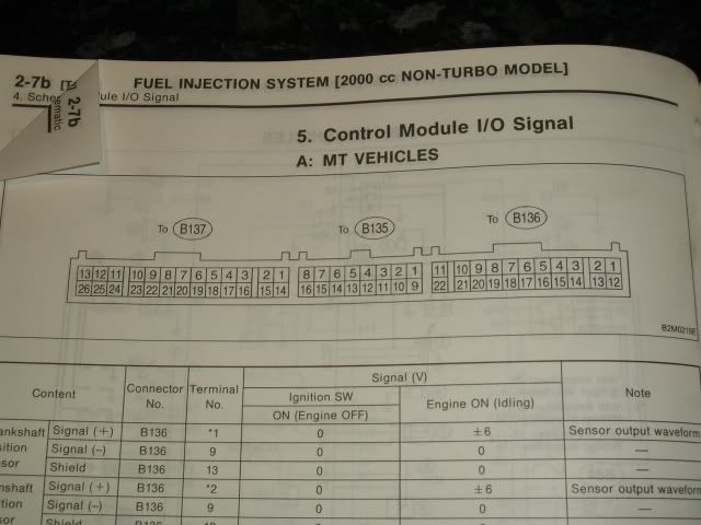
I have just looked at the computer plugs and found that the following wires are the ones that I need to find out what they do.
26 pin plug the following pin and colours:
22 red/white
18 blue
17 red/blue
16 green/red
16 pin plug
1 green/black
3 lt green/yellow
7 lt green/red
8 green/white
9 blue/yellow
12 red/black
13 orange
16 blue/green
Hopefully someone out ther can help.
26 pin plug the following pin and colours:
22 red/white
18 blue
17 red/blue
16 green/red
16 pin plug
1 green/black
3 lt green/yellow
7 lt green/red
8 green/white
9 blue/yellow
12 red/black
13 orange
16 blue/green
Hopefully someone out ther can help.

Hey 85wrx,
This is not real easy to follow, but may be some help... 1993 - 1996 Impreza Manual in PDF.
It's from one of those ebay cd's.
I'm putting the same motor in my brumby!
Daza.

This is not real easy to follow, but may be some help... 1993 - 1996 Impreza Manual in PDF.
It's from one of those ebay cd's.
I'm putting the same motor in my brumby!
Daza.
That seems to be the same information that I have come accross. It all relates to the DOHC MPFI Turbo motor. I am after one for the SOHC 2 ltr non turbo.
I have purchased those CD manuals off ebay myself. They state in there comments that it is for turbo and non turbo motors. I have yet to find one that includes the SOHC MPFI non turbo. Hopefully the latest one that I have purchased will have the wiring diagram that I require.
I have also tried to purchase the genuine workshop manual but with no luck. Subaru say it is not made anymore.
Thanks for the link to the pdf Daza, but not the one I am after.
Regards Darryl
I have had a look at this and it is different to this. Mine has an Air Flow meter not a map sensor.
All the pinouts for the select monitor, fans and check engine light state pins in my loom that are vacant. I would have to go through it all to get the pinouts that are wrong.
I guess it is because the Air flow meter difference.
All the pinouts for the select monitor, fans and check engine light state pins in my loom that are vacant. I would have to go through it all to get the pinouts that are wrong.
I guess it is because the Air flow meter difference.
I have had a better look and you are right about the AFM. Most of it looks to be similar but some of the positions are different. It helps to some degree. Do you have the wiring diagram for this. I may be able to use these in conjunction with what you have shown me to get this sorted out. Alot of the wires that I am still trying to trackdown aree not shown in the pinouts shown. Would it help if I emailed the ones that i now and don't know using the pin locator shown at the top.
Thanks regards Darryl
Thanks regards Darryl
Can you just post what connections you want to identify specifically?
Without knowing how the wiring was stripped from the harness it is hard to guage what you need to do to get it prepared for use. Does it have the Ignition and Fuel Pump relay still wired in?
Any info you can give is good and will help get it sorted out. It really isn't that hard with the right info and a bit of experience.