
I marked 8degBTDC on the case with the paint pen. I cheated a little and found a print out protractor on the internet, drew lines on it at 0deg and 8deg, found the distance between at roughly the radius of the pulley and marked it on the case. Should be right to within about 1deg. Good for a quick timing set.
The straw worked really well. It's soft enough not to scratch the piston or bore, totally rigid, and won't snap off inside the cylinder.
I would like an electronic distributor. I'd absolutely love an EDIS setup, but the crank sensor makes it a bit hard.
On the mech setup I have to say I don't replace the condensor unless it is suspect because the new ones aren't all that hot. Don't have a ballast resistor. GT40 built in. What do you mean by low voltage coil?
I got a couple of those wiring conduit brackets that nail into walls etc. today, yanked the nails and painted them. They will do nicely to keep some wiring off the accelerator cable. been cleaning up the bay a bit because everything was just sort of shoved on and messy as. Makes working in there really awkward.
EA81 Hitachi carb baseline or what is wrong?
-
TOONGA

- Elder Member
- Posts: 5340
- Joined: Sat May 30, 2009 10:15 am
- Location: Mandurah where they divided by zero
- Contact:
Ratcamper
the coils the work with ballast resistors and points are refered to as low voltage coils 30000-40000+ volts, the coils that work with electronic ignitions are refered to as high voltage coils 50000-70000+ volts.
Nice work with the protractor will be interesting to see how it works out
I forgot to mention the electronic dizzy has an internal module and you could always make up your own alternator bracket and remove the idler/ fan pulley and bracket completely.
eventually you will have to post some pictures of your graffiti / timing marks
TOONGA

Good info. Didn't know electronic ignitions had a higher spark voltage. That's always a good thing.TOONGA wrote:Ratcamper
the coils the work with ballast resistors and points are refered to as low voltage coils 30000-40000+ volts, the coils that work with electronic ignitions are refered to as high voltage coils 50000-70000+ volts.
Nice work with the protractor will be interesting to see how it works out
I forgot to mention the electronic dizzy has an internal module and you could always make up your own alternator bracket and remove the idler/ fan pulley and bracket completely.
eventually you will have to post some pictures of your graffiti / timing marks
TOONGA
I could make my own alternator bracket, but that seems a bit complex. I guess it'd also be possible just to lop the pulley off or something. There's a couple of Bosch alternators here that look like they may fit too. If the amps are higher, one may be in the motor's future.
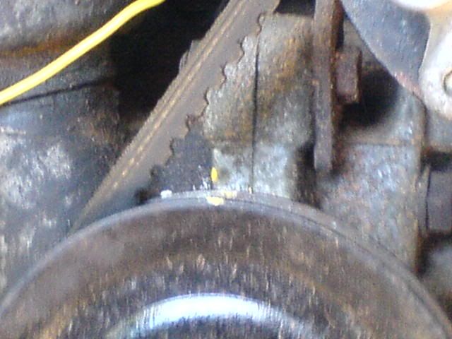
I have a crappy mobile phone pic of the timing marks:
-
TOONGA
- Elder Member
- Posts: 5340
- Joined: Sat May 30, 2009 10:15 am
- Location: Mandurah where they divided by zero
- Contact:
Im looking at the photo and Im trying to work out whre the timing marks are I can see the one on the pulley, is the yellow one on the engine the mark you are timing to ? or are there really fine lines that are blurred by the camera in the phone?RatCamper wrote:
From what I remember that lump of aluminium on the fan pully can be unbolted so the pulley is just a pulley.
TOONGA
The pulley mark is TDC when it is aligned with the case split. The case mark is 8deg BTDC. Pretty much an idiot proof timing setup. Perfect for me. If there were some nice solid mounting points it wouldn't be too hard to hack up a scrap of aluminium sheet or something to make a proper scale. Figuring out where to put the marks is easy. Mounting it is a little harder.
I've tried unbolting the aluminium lump on the pulley. I don't know who did it up but it's on there pretty tight. After that I got a little worried that it was also a bearing housing cap or something and left it. Another crack is due perhaps. It'll still be a funny looking pulley like a cotton spool but it would be nice to have the lump gone.
There are a few things that have to be done with the motor setup. It's mostly all mounting work. Besides that it's just the carb and some welding to fix some exhaust holes. That's the good thing about it running super rich for a bit. All the exhaust holes are clearly marked.
-
El_Freddo

- Master Member
- Posts: 12708
- Joined: Tue Oct 04, 2005 10:00 am
- Location: Bridgewater Vic
- Contact:
Rat Camper - if you want to rid your EA of the idler pulley that used to be for the mechanical fan you can just remove it and run with a different sized belt to make up for the slack of the original one like this:

Pic take from the death cab blog.
Or find the cast iron AC pump bracket and just run the alternator without the AC or idler pulleys
Cheers
Bennie
Pic take from the death cab blog.
Or find the cast iron AC pump bracket and just run the alternator without the AC or idler pulleys
Cheers
Bennie

-
littlewhiteute

- Junior Member
- Posts: 623
- Joined: Sat Sep 30, 2006 7:22 am
- Location: Brisbane
I want to know why you are doing this and not using the marks on the flywheel?RatCamper wrote:I marked 8degBTDC on the case with the paint pen. I cheated a little and found a print out protractor on the internet, drew lines on it at 0deg and 8deg, found the distance between at roughly the radius of the pulley and marked it on the case. Should be right to within about 1deg. Good for a quick timing set.
The straw worked really well. It's soft enough not to scratch the piston or bore, totally rigid, and won't snap off inside the cylinder.
I would like an electronic distributor. I'd absolutely love an EDIS setup, but the crank sensor makes it a bit hard.
On the mech setup I have to say I don't replace the condensor unless it is suspect because the new ones aren't all that hot. Don't have a ballast resistor. GT40 built in. What do you mean by low voltage coil?
I got a couple of those wiring conduit brackets that nail into walls etc. today, yanked the nails and painted them. They will do nicely to keep some wiring off the accelerator cable. been cleaning up the bay a bit because everything was just sort of shoved on and messy as. Makes working in there really awkward.
Timing light through the aperture on the drivers side of the bellhousing.
Regards
Gary
Gary
-
TOONGA
- Elder Member
- Posts: 5340
- Joined: Sat May 30, 2009 10:15 am
- Location: Mandurah where they divided by zero
- Contact:
RatCamper wrote: I don't know what the engine is timed to. I have to figure it out as I don't have a stock flywheel or flywheel housing. There is a mark on the crankshaft pulley but I don't know what it means yet. I hope it is for 8deg btdc.
it doesnt have the stock flywheel or bellhousinglittlewhiteute wrote:I want to know why you are doing this and not using the marks on the flywheel?
Timing light through the aperture on the drivers side of the bellhousing.
TOONGA
-
littlewhiteute
- Junior Member
- Posts: 623
- Joined: Sat Sep 30, 2006 7:22 am
- Location: Brisbane
that's interesting. What's going on there? It looks like the shaft from the idler was pulled out somehow. And i see there is supposed to be some kind of shim between the bracket on the left side under the alternator and the engine case. I'm missing that shim.El_Freddo wrote:Rat Camper - if you want to rid your EA of the idler pulley that used to be for the mechanical fan you can just remove it and run with a different sized belt to make up for the slack of the original one like this:
Pic take from the death cab blog.
Or find the cast iron AC pump bracket and just run the alternator without the AC or idler pulleys
Cheers
Bennie
I've already got a shorter belt. The PO of the motor bought it in error. I tried to put it on and realised.
Not much space in that beetle engine bay. Wow. I ended up with so much space after putting the EA in that I'm considering pulling apart a belt driven compressor I have, mounting the tank in the space behind the motor, and putting the compressor on the motor. the compressor was built from old truck parts if you are wondering. It's not one of those flash ones.
Back to that photo. it's interesting the oil pressure sender is in a different location.
I realised I'll have to run the Hitachi carb for blue slip. Things like the coasting valve etc. won't connect too well otherwise.
Gooking at the gregory's the motor seems to be pretty early but some of the vac lines suggest later.
-
El_Freddo
- Master Member
- Posts: 12708
- Joined: Tue Oct 04, 2005 10:00 am
- Location: Bridgewater Vic
- Contact:
maybe they cut it off or it wasn't there in the first place. The shim that I think you're talking about would be a brace from the alternator bracket to the head for extra support and most likely to eliminate vibration.
With this engine you have to realise that it may have been from a later model MY, thus the different oil pressure sender unit mounting position - it could be an aftermarket oil pump for all we know!
Food for thought either way!
Cheers
Bennie
With this engine you have to realise that it may have been from a later model MY, thus the different oil pressure sender unit mounting position - it could be an aftermarket oil pump for all we know!
Food for thought either way!
Cheers
Bennie
-
TOONGA
- Elder Member
- Posts: 5340
- Joined: Sat May 30, 2009 10:15 am
- Location: Mandurah where they divided by zero
- Contact:
that engine is a "super" engine as it has blue rocker covers, later model EA81 motors had black rocker covers when they went to unleaded.
the oil sender is a pressure sender thats used with a pressure gauge on the dash and is more than likely from a touring wagon circa 83-84, there is a bung in the bottom of the oil pump that can be removed and a sender can be fitted to be used with an aftermarket pressure gauge.
TOONGA
the oil sender is a pressure sender thats used with a pressure gauge on the dash and is more than likely from a touring wagon circa 83-84, there is a bung in the bottom of the oil pump that can be removed and a sender can be fitted to be used with an aftermarket pressure gauge.
TOONGA
Yeah! I have a super engine! Sorry I just like that. Assuming the rocker covers are OE then I think it is. The rocker covers and the air cleaner were painted black by someone and I can see blue underneath.
The shim is pretty much that. It's the thing that goes between the alternator brace and the pulley. Why they did it like that i don't know. I do know that bit is missing.
My idiot light sender is on the end of the oil filter "shaft". Is that position pressure gauge friendly, or is it affected by some other force like a pressure relief or something?
I'd like to fit one of those two in one idiot light and pressure senders. I have a damaged one kicking around that I could use as a size guide I guess.
It's late. I'm tired. I hope this wasn't a rambling post. thanks for all your help so far. Are there any photos i can take that would aid in identifying the model of motor? It has a bearing on teh crap i need to fit for blue slip.
What a day!
Long story short, I wanted to start it but couldn't. Seemed like a flattish battery. It did an initial pop and then struggled desperately to crank the motor.
Cue lots of stuffing around, charging battery, checking voltages, priming the fuel system etc.
Many hours later, a few times on the charger and a static timing job later I realised what the problem was. I popped the distributor cap and sure enough the rotor looked a little odd. sitting slightly askew. I pulled it off with great difficulty. It had dislodged and got snagged. After a few failed attempts at getting it to stay put it did, and I got all the unburnt fuel cleared out and the motor started. Add a rotor to the list.
Good news! I found a good price on a Weber adapter kit from a Redline Weber supplier. A proper one that doesn't involve me trying to offset drill the holes in the manifold.
I have been assured by the person at Redline that the Holley licensed carburettor I want to put on is sub-optimal and won't flow freely enough but will be better than the Hitachi.
Surprisingly the synchronous Webers like the DGAS are the best type for the EA81.
If I had some correct flanges and some tube lying around ...and a few other bits I'd love to fit the OE 1800 duals which I pulled off the VW. I pulled them off in the first pplace because the cost or rebuild kits were prohibitive. Only recently I found them in the U.S. for about 1/10 the price. I wasn't going to pay $400 for a couple of kits.
A while back I did some simple, I mean really really simple flow calculations and figured that the VW duals flow better than a Weber progressive. The VW carbs are also an utter bastard to tune. 3 idle systems plus having to deal with synchronization.
Maybe that could be a project for later.
I wouldn't hesitate in putting the Weber, sorry Holley straight on if it wasn't for that Coasting mixture enrichment dealy. Unless that's what the mysterious plugged fitting on the Weber is for which is very doubtful, it'd be non functional and not good for a blue slip.
Can I ask what the people that went Weber did for an air filter? About the best solution I can come up with is use the air horn adapter thing I have, get something right angle either from supercheaps ricer section, find something at a wrecker or improvise like mad and use the EFI cannister air cleaner I pulled from the Magna.
I saw an awesome looking right angle metal adapter thing that bolts to the top of a Weber on the datto 1200 site I think it was, which would be great but it's the only one I have ever seen.
-
TOONGA
- Elder Member
- Posts: 5340
- Joined: Sat May 30, 2009 10:15 am
- Location: Mandurah where they divided by zero
- Contact:
Ratcamper it took me a little bit of searching but this is what preno did
showthread.php?t=17673&page=4
I would love to see a picture of your weber as well it may help in telling you where the extra vacuum lines could go for the blue slip
TOONGA
showthread.php?t=17673&page=4
I would love to see a picture of your weber as well it may help in telling you where the extra vacuum lines could go for the blue slip
TOONGA
Thanks for that. hard to make out the hoses but the air filter mod is sure interesting.
Agh photobucket is being a huge pain. I'll get there...
Some photos:
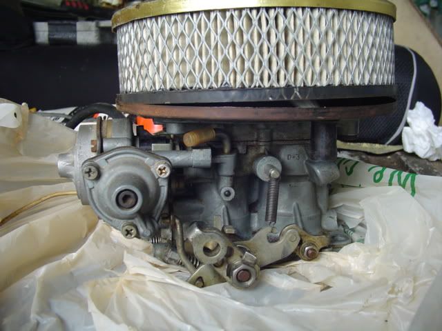
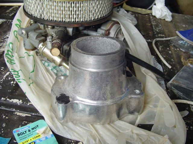
Bonus shot of air horn adapter. two of the holes are filled with gunk because the Holley only uses two studs. Keeping my future options open.
You can see the plugged line on the first photo.
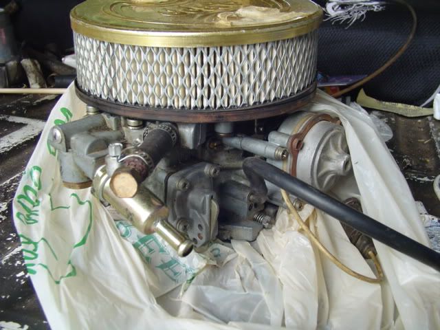
In the second one I'm a little unclear of the purpose of the big plugged one. It's either a return line or a bowl vapour vent line.
The one with the bit of hose hanging off is vac advance.
Agh photobucket is being a huge pain. I'll get there...
Some photos:
Bonus shot of air horn adapter. two of the holes are filled with gunk because the Holley only uses two studs. Keeping my future options open.
You can see the plugged line on the first photo.
In the second one I'm a little unclear of the purpose of the big plugged one. It's either a return line or a bowl vapour vent line.
The one with the bit of hose hanging off is vac advance.
-
TOONGA
- Elder Member
- Posts: 5340
- Joined: Sat May 30, 2009 10:15 am
- Location: Mandurah where they divided by zero
- Contact:
would be nice to see it out of the plastic bag and without the air cleaner
the the pipe at the top with the big bolt blocking the hole "bowl vapour vent line" goes to the the charcoal canister, the smaller pipe blocked with the factory bung could be used for the "Coasting mixture enrichment dealy" as it is in the same approximate height as the one on the hitachi
not sure if I gave you this link before but if you scroll down to installation (don't click on the blue links as the hyperlinks don't work anymore)
http://www.subarubrat.com/Retrofitting% ... V%2032.htm
it will show you the basic setup for pollution
TOONGA