MY/L series rear wheel bearing tool

General Subaru Talk - Media / News / Stories ...
Post Reply
User avatar
Silverbullet
Senior Member
Posts: 2921
Joined: Mon Aug 23, 2010 6:20 pm
Location: Adelaide

MY/L series rear wheel bearing tool

Post by Silverbullet » Mon Jun 30, 2014 4:39 pm

Yes the weird nut on the inside with only 2 parallel slots for drive.

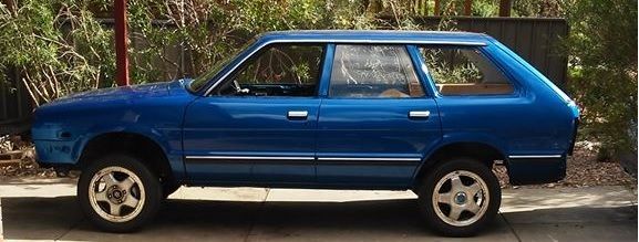
I've seen some creative solutions to this little problem on this site before, and when I came to replacing the rear wheel bearings on my wagon I thought 2 pieces of flat bar weren't going to cut it :rolleyes: Although perfectly sufficient I'm sure, some guys don't leave home without theirs. So I decided to do it the way I know how and machine a purpose made tool. Found enough scraps at work and got a spare half an hour.

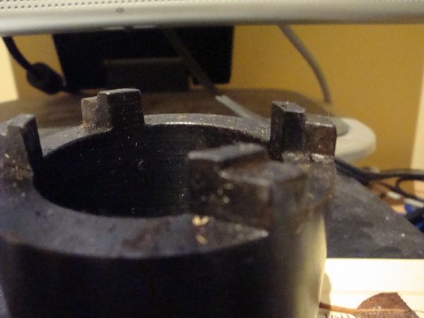
The drive end was a piece of hollow round bar bored out to slightly smaller diameter than the inside of the nut itself. Outside diameter turned to .5mm larger than the OD of the nut. Then the drive teeth machined out on the milling machine to 5mm deep, perfect fit! I put a big chamfer on one end as a welding prep and welded it to a piece of thick wall compressed air pipe that happened to be the perfect diameter. Then turned a big thick washer to weld at the other end, with a hole in it in which to weld a 1/2" drive sacrificial socket.

And it works well! well mostly anyway. If I did it again I would make it half the length it is or less. I didn't have the stub axles with me at work when I made this so had no idea how long to make it. As it is it's impossible to use with the rear hubs on the car. Being so long it's very easy for it to tilt and slip off the nut, smacking your fist into another part of the car. Also I would not bore out the insides to large. I would make the internal diameter a neat fit around the stub axle itself, to act as a guide.

Anyway have some pics:

Image
Image
Image
Image
Will it ever end!?
-EA81 TWIN CARB!!!!
-L series 5 speed
-Custom paint job
-2" lift
-Full custom re-wire
-L series front end
Image

User avatar
FujiFan
Junior Member
Posts: 494
Joined: Sun Oct 31, 2010 8:32 pm
Location: CentralCoast NSW

Post by FujiFan » Mon Jun 30, 2014 5:25 pm

Nice job SB. What grade of steel you use? Would you be interested in making another, albeit with the improvements you explained. I would be keen to buy :)

User avatar
henpecked
Junior Member
Posts: 449
Joined: Fri Dec 05, 2008 7:20 pm
Location: South Oz

Post by henpecked » Mon Jun 30, 2014 5:53 pm

I would be in for 2 :) , the second one for when I lost the first :mad:

User avatar
Silverbullet
Senior Member
Posts: 2921
Joined: Mon Aug 23, 2010 6:20 pm
Location: Adelaide

Post by Silverbullet » Mon Jun 30, 2014 6:37 pm

It's just plain old mild steel, plenty good enough for this job and easier to weld. Sadly it's unlikely I would be able to make any more, place where I work is not friendly towards outside projects. If I had my own lathe it would be different :(
Will it ever end!?
-EA81 TWIN CARB!!!!
-L series 5 speed
-Custom paint job
-2" lift
-Full custom re-wire
-L series front end
Image

User avatar
steptoe
Master Member
Posts: 11582
Joined: Thu Oct 06, 2005 10:00 am
Location: 14 miles outside Gotham City

Post by steptoe » Mon Jun 30, 2014 6:45 pm

I got one through our buying agent in the the US, so no credit for making it.

OD is 62mm, wall thickness is ~9mm

about 32.5mm max between outside of a pair of those teeth

each tooth must be 1/4" thick (coz I forgot to buy the battery for the verniers today :( 6.05mm ?)

and the teeth aren't just flat on top, it's like they were 8.2mm tall but inner 4.0mm remains while about 5.0mm, so is stepped from 8.2mm to 5mm - if you get what I mean without a camera and pair of gloves

Total tool height is 61mm and with a square hole for 1/2" drive

weighs 700grams !

no idea why the step

Image

make up an order sheet, get the boss to give you the time to make them and charge reasonable cost ?

User avatar
FujiFan
Junior Member
Posts: 494
Joined: Sun Oct 31, 2010 8:32 pm
Location: CentralCoast NSW

Post by FujiFan » Mon Jun 30, 2014 6:45 pm

D'oh!
Well if when you get some spare time at work, think of me;) I'm sure you can cover your tracks with regards to a production line/repeat manufacturing :)

User avatar
Silverbullet
Senior Member
Posts: 2921
Joined: Mon Aug 23, 2010 6:20 pm
Location: Adelaide

Post by Silverbullet » Mon Jun 30, 2014 8:19 pm

Jonno I can't quite picture it :???: Why would the teeth need to be stepped? Can't remember the dimensions I used off the top of my head, I can get a CAD drawing/dxf for the business end if anyone is interested in making one themselves.

Hehe sorry Jay, usually when I sneak a little home job in the boss man is on my case within minutes. Got lucky this time around I guess.
Will it ever end!?
-EA81 TWIN CARB!!!!
-L series 5 speed
-Custom paint job
-2" lift
-Full custom re-wire
-L series front end
Image

User avatar
El_Freddo
Master Member
Posts: 12637
Joined: Tue Oct 04, 2005 10:00 am
Location: Bridgewater Vic
Contact:

Post by El_Freddo » Wed Jul 02, 2014 9:52 pm

Silverbullet wrote:Jonno I can't quite picture it :???: Why would the teeth need to be stepped?
Probably so that the thread inside the hub isn't damaged if the nut goes in that far so that the tool fouls on it.

SB - that's a much more professional looking tool than mine - I've made mine so that I need to remove the axle first as the tool goes into the hub...

Cheers

Bennie
"The lounge room is not a workshop..."
Image
El Freddo's Pics - El_Freddo's youtube

User avatar
Silverbullet
Senior Member
Posts: 2921
Joined: Mon Aug 23, 2010 6:20 pm
Location: Adelaide

Post by Silverbullet » Thu Jul 03, 2014 12:43 am

Since Jonno added that photo in an old post the thread didn't update, now I see why it is stepped, to guide the teeth using the ID of the nut. Much more economical on metal than my idea of using the stub axle as a guide. Well I wasn't far off anyway! I can see the boss man now, if I walked in with an idea like this to make these. Sadly it's the sort of place where they say no, and that's the end of it....unless I come in early or stay late and I already get up early enough and get home late enough...now I'm rambling :rolleyes:

Bennie how can you tighten the nut up without the axle in place? The stub axle is part of the bearing assembly sequence isn't it? Press outer races into trailing arm, press one inner race onto axle, place axle inside outer race, press other inner race onto other end, this nut holds it all together.
Will it ever end!?
-EA81 TWIN CARB!!!!
-L series 5 speed
-Custom paint job
-2" lift
-Full custom re-wire
-L series front end
Image

User avatar
El_Freddo
Master Member
Posts: 12637
Joined: Tue Oct 04, 2005 10:00 am
Location: Bridgewater Vic
Contact:

Post by El_Freddo » Sat Jul 05, 2014 9:48 pm

Silverbullet wrote:Bennie how can you tighten the nut up without the axle in place? The stub axle is part of the bearing assembly sequence isn't it? Press outer races into trailing arm, press one inner race onto axle, place axle inside outer race, press other inner race onto other end, this nut holds it all together.
The hub nut holds the outer race in place within the hub. The stub axle is actually the bit that holds it all together with the cone washer/hub/castle nut.

I've done a number of bearing replacements without an issue - I think I'm about to do Ruby Scoo's rear bearings again soon...

Cheers

Bennie
"The lounge room is not a workshop..."
Image
El Freddo's Pics - El_Freddo's youtube

Post Reply

Return to “Subaru Chat”