
EA81S - yeah !!
Silverbullets' resto: Engine, gearbox, suspension


-
Silverbullet

- Senior Member
- Posts: 2873
- Joined: Mon Aug 23, 2010 6:20 pm
- Location: Adelaide
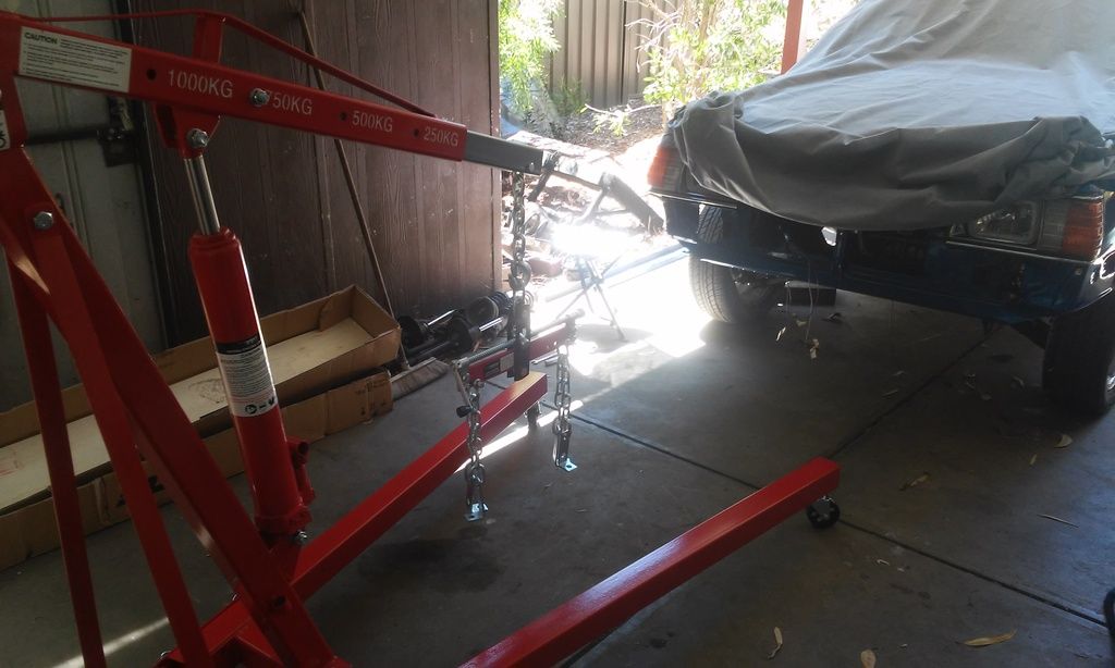
Today a milestone was achieved
Nearly 4 years have passed since I first laid my hands on this engine, got it rebuilt, and stored it away under a sheet at the back of the shed until I'd built a car worthy of putting it into. At the time I had no idea what was ahead, since this project has snowballed so much from what I envisaged when I started. But today the precious lump was brought out of storage and put in its final resting place
At 10 AM this morning I was uhm-ing and err-ing about buying an engine crane (I usually borrow one from a guy I know but couldn't get in touch with him) and 8 hours later the engine is in I was quite desperate to get to work on putting the engine in this week, so I just bit the bullet and got the crane. We were desperately short on space for storing this thing (and it is a monster) so I got it with the thought that if it didn't work out I could flog it on again and nearly get my money back. But I figure if I just dismantle it when I'm done we can tuck it away under a shelf.
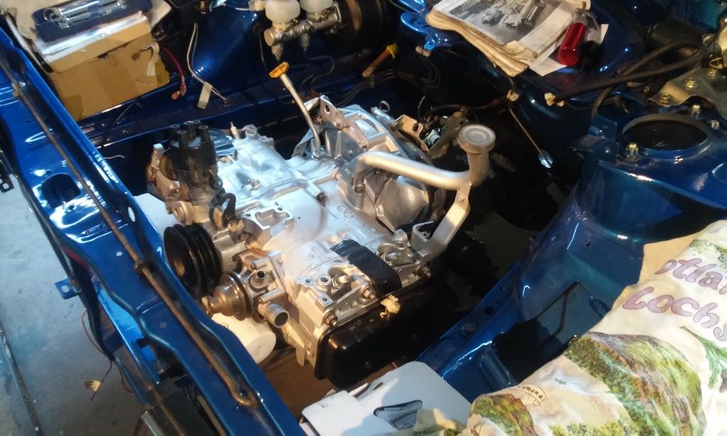
Anyway, here it is, sorry for the blurry pics I'm not sure why that happened. Got it in on the second try, after clutch alignment troubles (its incredible how accurately the clutch needs to be lined up, and cos it's L series my usual clutch tool didn't work) Second try though, it slotted in nicely. New OEM engine mounts popped into the x-member nicely and we were done also the gearbox seems to have pulled up a bit more straight now.
An important moment
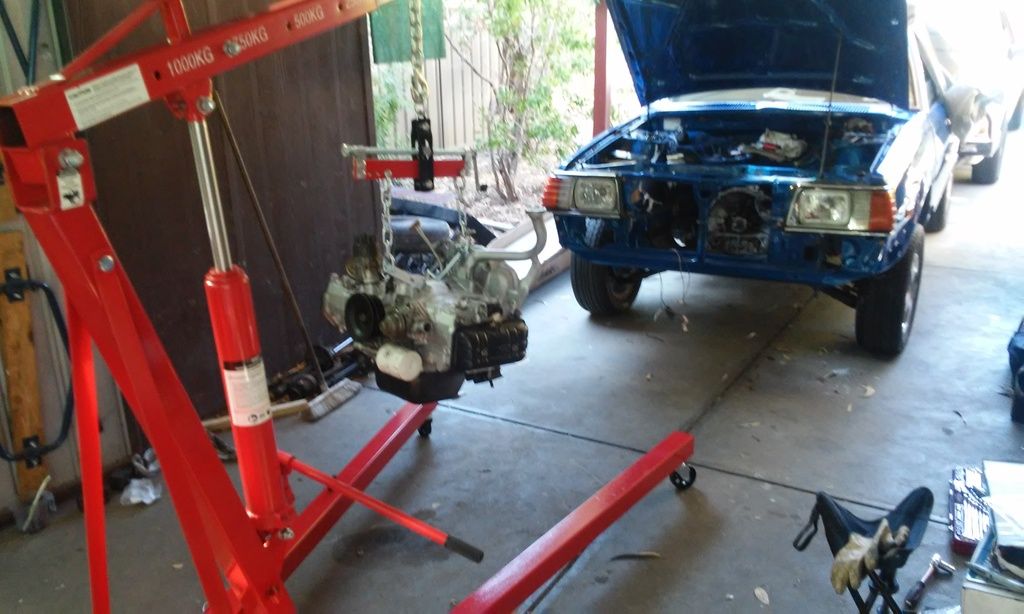
Finally! the old girl has a heart again
Nearly 4 years have passed since I first laid my hands on this engine, got it rebuilt, and stored it away under a sheet at the back of the shed until I'd built a car worthy of putting it into. At the time I had no idea what was ahead, since this project has snowballed so much from what I envisaged when I started. But today the precious lump was brought out of storage and put in its final resting place
At 10 AM this morning I was uhm-ing and err-ing about buying an engine crane (I usually borrow one from a guy I know but couldn't get in touch with him) and 8 hours later the engine is in
Anyway, here it is, sorry for the blurry pics I'm not sure why that happened. Got it in on the second try, after clutch alignment troubles (its incredible how accurately the clutch needs to be lined up, and cos it's L series my usual clutch tool didn't work) Second try though, it slotted in nicely. New OEM engine mounts popped into the x-member nicely and we were done
An important moment
Finally! the old girl has a heart again
Will it ever end!?
-EA81 TWIN CARB!!!!
-L series 5 speed
-Custom paint job
-2" lift
-Full custom re-wire
-L series front end
-EA81 TWIN CARB!!!!
-L series 5 speed
-Custom paint job
-2" lift
-Full custom re-wire
-L series front end
-
Proton mouse
- Junior Member
- Posts: 378
- Joined: Mon Nov 06, 2006 11:35 pm
- Location: Diagonally parked in a parallel universe
-
Silverbullet
- Senior Member
- Posts: 2873
- Joined: Mon Aug 23, 2010 6:20 pm
- Location: Adelaide
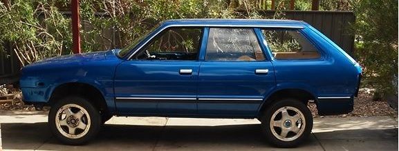
No noticeable dropProton mouse wrote: How does the suspension sit now?
Will it ever end!?
-EA81 TWIN CARB!!!!
-L series 5 speed
-Custom paint job
-2" lift
-Full custom re-wire
-L series front end
-EA81 TWIN CARB!!!!
-L series 5 speed
-Custom paint job
-2" lift
-Full custom re-wire
-L series front end
-
Proton mouse
- Junior Member
- Posts: 378
- Joined: Mon Nov 06, 2006 11:35 pm
- Location: Diagonally parked in a parallel universe
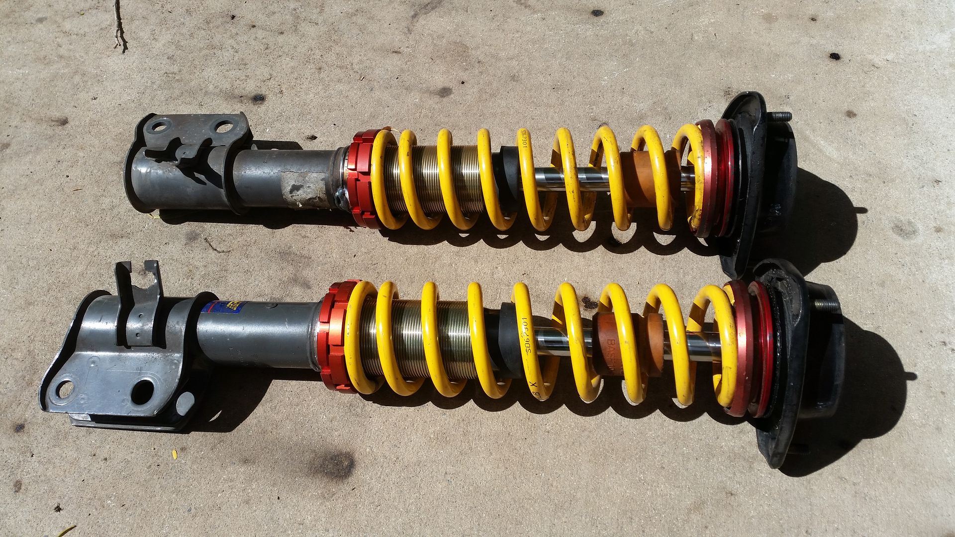
What about getting the struts made adjustable?
I had these professionally made up for the Brumby.
They are Liberty to suit my brake/wheel/hub set up, but the same could be done for your L struts.
I supplied the struts. The suspension shop supplied the narrow King springs, supplied (and welded on) the threaded spring support tube. Supplied the adjuster nuts, lock rings and upper spring seat. Plus also modded the liberty strut top so it could accept the upper spring seat. All up $500, but I know you with your skill set could do the work and save a lot. If I had have shopped around I could have got it cheaper too, but was being impatient at the time.
Cheers JB

-
steptoe
- Master Member
- Posts: 11582
- Joined: Thu Oct 06, 2005 10:00 am
- Location: 14 miles outside Gotham City
Lookin' so much better Sam. That bonnet stay gonna see some yellow zinc plating at some stage ? Dare I mention the twin ports first turning - was the cause ever determined?
Nearly went to buy one of those engine cranes some years ago, but walking up to an assembled one, wondering where it was gonna go , stopped me in my tracks. Maybe if you rent it out it will stay out more than in ??
Nearly went to buy one of those engine cranes some years ago, but walking up to an assembled one, wondering where it was gonna go , stopped me in my tracks. Maybe if you rent it out it will stay out more than in ??
-
Silverbullet
- Senior Member
- Posts: 2873
- Joined: Mon Aug 23, 2010 6:20 pm
- Location: Adelaide
John, I love that pic Sounds like it was an easy thing for you then, I haven't really thought about going to a professional, maybe I should. I'm not sure who I would even go to, it would have to be a specialty suspension place yes? Ah, now I remember...I did try and get the front struts looked at way back when I started working on them, I found a specialty suspension place, went there during business hours but all was locked up. I asked the next shop along, was told the suspension guru had a car accident the previous week and was seriously injured, wouldn't be back for who knows how long  Hence I tried to work it out myself.
Jonno, cause of what exactly? The bonnet stay does need some attention...I think rocker covers and all A/C and P/steering bracketry will get some love at the same time (sand blast and re-coating of some sort)
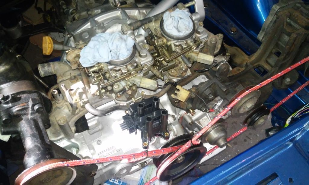
Last few days I've been working on locating all the components for my EDIS setup. I've decided the sensor my kit came with is a horrible design so I've ordered a new one with a right angled sensing tip. The sensor needs to be mounted before I can work out the position of the toothed trigger wheel on the crank pulley. So while the sensor is on its way I've been making brackets for the EDIS module and new coil pack.
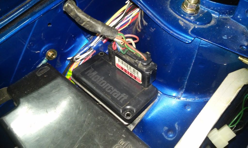
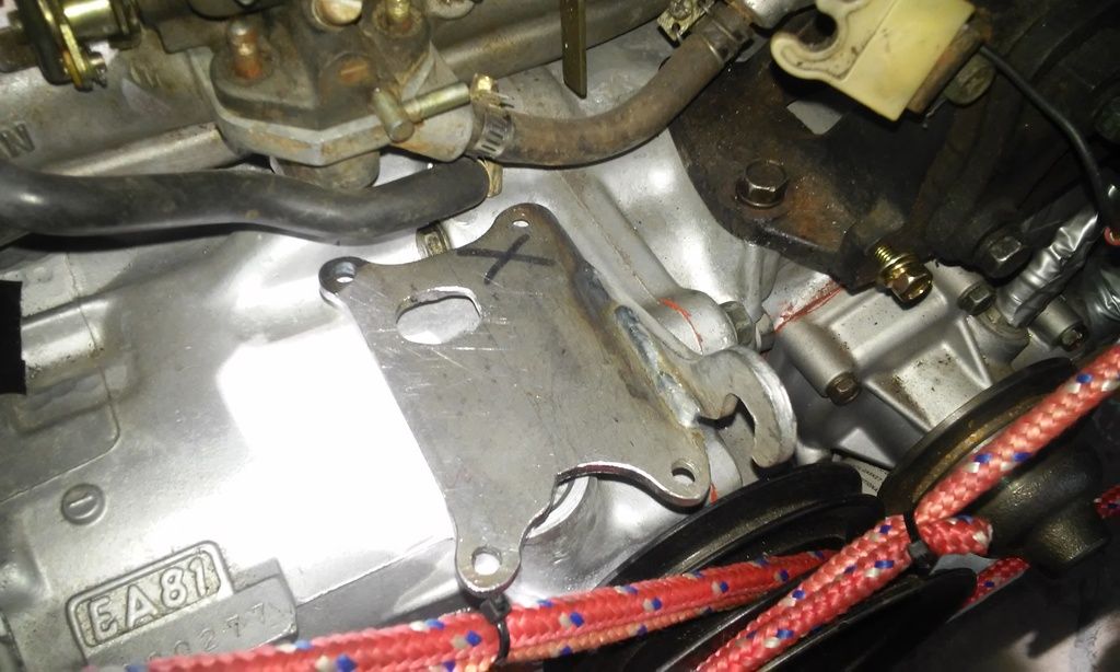
Been scratching my head for weeks wondering where I was gonna put the coil pack and EDIS module, there's no decent flat spots anywhere in the engine bay with enough room, behind the pisser bottle maybe but that would mean huge HT leads, no good. I've got all my bracketry and manifold/carbies mocked up on the engine to get locations of things, then noticed a conspicuous empty space where the dizzy used to be...bingo! It'll even look quite stock with the HT leads originating from that area. As for the EDIS module, there was a module sized gap next to my fuse box where the old ignition coil usually lives, that will do nicely.
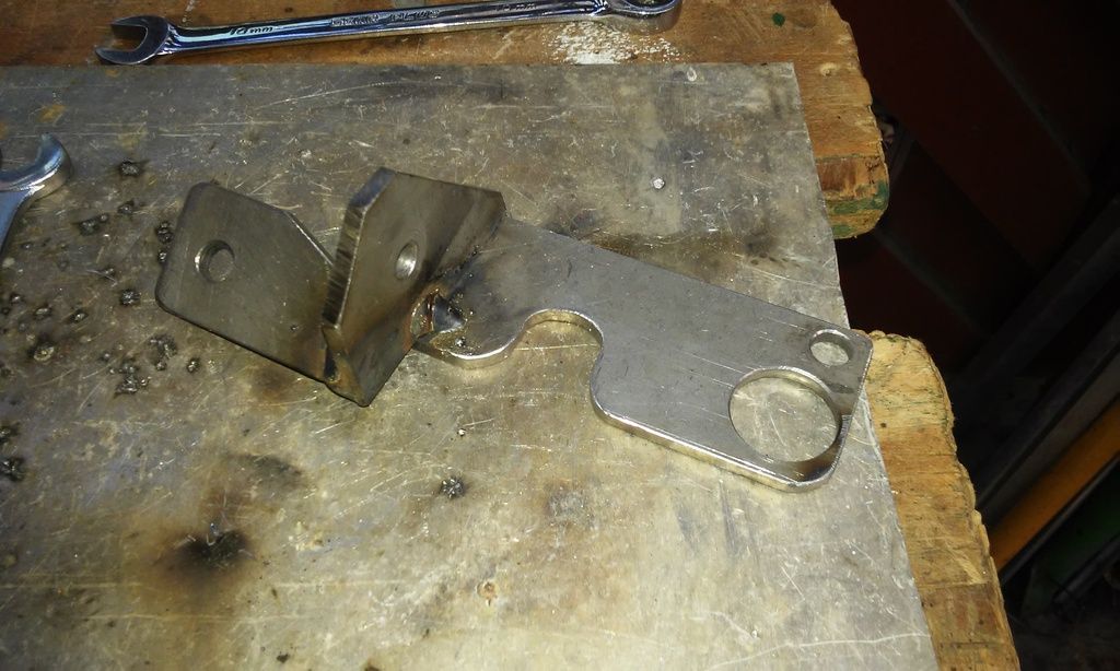
With some CAD (cardboard aided design) and many hours of cutting, grinding, filing, drilling and welding I've come up with these:
Note access hole for a 10mm socket
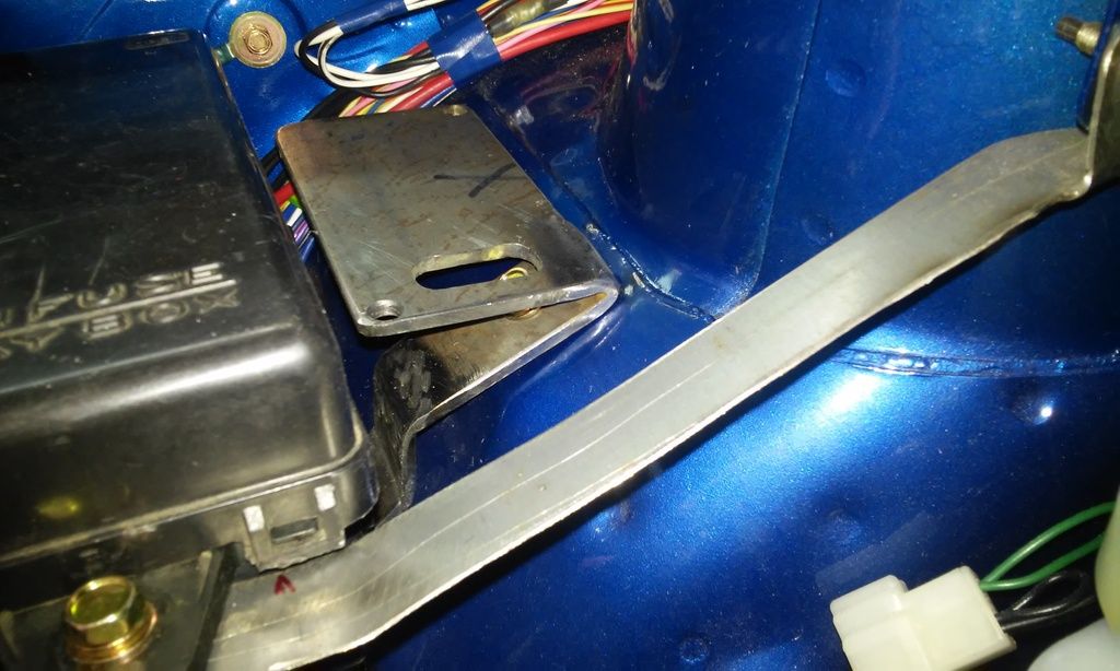
Perfect! note: that module isn't wired up yet, the pig tail of wires included with it just looks like its disappearing into the fender.
I'm utilizing the stock lifting hook for this one, as well as the m6 bolt underneath where the dizzy bracket usually bolts on as an extra support and to stop the platform vibrating. I'll also get a plug made up with an O-ring to seal inside the usual dizzy hole, maybe attach it to my new bracket somehow to keep it in and seal the crank case.
Jonno, cause of what exactly? The bonnet stay does need some attention...I think rocker covers and all A/C and P/steering bracketry will get some love at the same time (sand blast and re-coating of some sort)
Last few days I've been working on locating all the components for my EDIS setup. I've decided the sensor my kit came with is a horrible design so I've ordered a new one with a right angled sensing tip. The sensor needs to be mounted before I can work out the position of the toothed trigger wheel on the crank pulley. So while the sensor is on its way I've been making brackets for the EDIS module and new coil pack.
Been scratching my head for weeks wondering where I was gonna put the coil pack and EDIS module, there's no decent flat spots anywhere in the engine bay with enough room, behind the pisser bottle maybe but that would mean huge HT leads, no good. I've got all my bracketry and manifold/carbies mocked up on the engine to get locations of things, then noticed a conspicuous empty space where the dizzy used to be...bingo!
With some CAD (cardboard aided design) and many hours of cutting, grinding, filing, drilling and welding I've come up with these:
Note access hole for a 10mm socket
Perfect! note: that module isn't wired up yet, the pig tail of wires included with it just looks like its disappearing into the fender.
I'm utilizing the stock lifting hook for this one, as well as the m6 bolt underneath where the dizzy bracket usually bolts on as an extra support and to stop the platform vibrating. I'll also get a plug made up with an O-ring to seal inside the usual dizzy hole, maybe attach it to my new bracket somehow to keep it in and seal the crank case.
Will it ever end!?
-EA81 TWIN CARB!!!!
-L series 5 speed
-Custom paint job
-2" lift
-Full custom re-wire
-L series front end
-EA81 TWIN CARB!!!!
-L series 5 speed
-Custom paint job
-2" lift
-Full custom re-wire
-L series front end
-
Silverbullet
- Senior Member
- Posts: 2873
- Joined: Mon Aug 23, 2010 6:20 pm
- Location: Adelaide
It was around here when I was nearly finishing the coil pack bracket, was putting that m6 screw in where the dizzy usually bolts, was bolting down a right angle piece to locate on the platform for a quick tack, within one turn of the handle there was a slight tight spot then *pop*
...the brand new bolt had just snapped off in the hole :evil::evil:
Couldn't believe my eyes, did this just happen to ruin my productive streak and piss me off? A brand new bolt FFS!!!! The head just fell off with little to no torque on it.
There's not enough sticking out of the block to grab onto or weld a nut on. So I downed tools, packed everything up and walked away. I'll go and buy an M6 helicoil set tomorrow.
...the brand new bolt had just snapped off in the hole
Couldn't believe my eyes, did this just happen to ruin my productive streak and piss me off? A brand new bolt FFS!!!! The head just fell off with little to no torque on it.
There's not enough sticking out of the block to grab onto or weld a nut on. So I downed tools, packed everything up and walked away. I'll go and buy an M6 helicoil set tomorrow.
Will it ever end!?
-EA81 TWIN CARB!!!!
-L series 5 speed
-Custom paint job
-2" lift
-Full custom re-wire
-L series front end
-EA81 TWIN CARB!!!!
-L series 5 speed
-Custom paint job
-2" lift
-Full custom re-wire
-L series front end
Steptoe yellow Zinc Cromate has been banned for a while, have you noticed all new nuts and bolts are now nickel plated, Premium NOS Zinc Chromate nuts and bolts will soon skyrocket in price as the "restorers" start hunting them down.steptoe wrote:Lookin' so much better Sam. That bonnet stay gonna see some yellow zinc plating at some stage ? Dare I mention the twin ports first turning - was the cause ever determined?
Nearly went to buy one of those engine cranes some years ago, but walking up to an assembled one, wondering where it was gonna go , stopped me in my tracks. Maybe if you rent it out it will stay out more than in ??
Nickel plating you can do at home, a guy up newcastle way sells a kit for about $150.00 last time I checked.Really finishes off a Job all shiny refurbed Factory fittings.
Bummer about new bolts breaking, Be especially careful about anything store bought in stainless as well should you feel the urge, I have lost count of thre number of staino fastenings I have come across that seize and gall when you try to remove them even when never seize was used.
Stainless bolts and nuts on BMW Motorcycles never seize or gall because they are hardened wheras most store bought stainless is not heat treated to harden them and stop them galling and remember they always screw in OK not so nice coming undone unless they are manufacture OE fittings made the right way.

-
Silverbullet
- Senior Member
- Posts: 2873
- Joined: Mon Aug 23, 2010 6:20 pm
- Location: Adelaide
Coxy, nice to know about stainless fasteners. I wondered about them, whether they would seize in an aluminium hole. I bought some stainless phillips machine screws in the smaller sizes (M3, M4, M5) for use on the interior. All other bolts where the originals were gold colored I'm replacing with new from a nuts and bolts kit I bought online, they haven't let me down until now
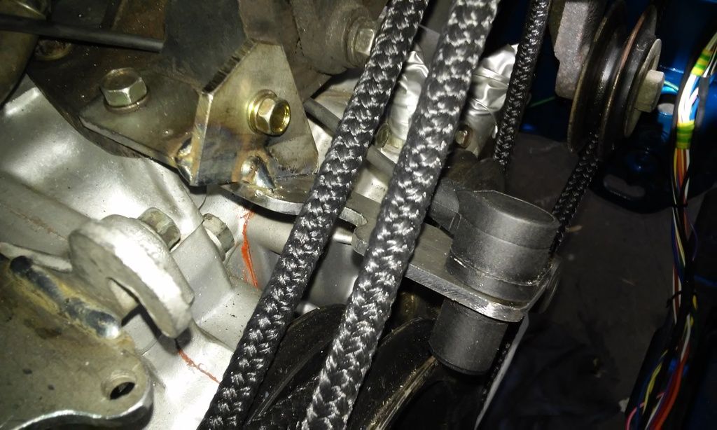
Bantum, that's 4mm mild steel plate. I had it lying around, but I like it for these kinds of brackets because its thick enough to help prevent vibrations damaging electrical bits (better than 3mm) but also thin enough to still work with hand tools and an angle grinder. Anyone else might have trouble buying that thickness though, it was scrap off a coil from my old work. Should have mentioned, the rope is so I can visualize where the belts are going to be so I don't hit any of them Wish I had an old alternator lying around to test fit but I can't seem to find one.
Bantum, that's 4mm mild steel plate. I had it lying around, but I like it for these kinds of brackets because its thick enough to help prevent vibrations damaging electrical bits (better than 3mm) but also thin enough to still work with hand tools and an angle grinder. Anyone else might have trouble buying that thickness though, it was scrap off a coil from my old work. Should have mentioned, the rope is so I can visualize where the belts are going to be so I don't hit any of them
Will it ever end!?
-EA81 TWIN CARB!!!!
-L series 5 speed
-Custom paint job
-2" lift
-Full custom re-wire
-L series front end
-EA81 TWIN CARB!!!!
-L series 5 speed
-Custom paint job
-2" lift
-Full custom re-wire
-L series front end
-
steptoe
- Master Member
- Posts: 11582
- Joined: Thu Oct 06, 2005 10:00 am
- Location: 14 miles outside Gotham City
mate ! Looking better each time you show us Sam. Maybe I should not mention the rising distributor - was this twin port wasn't it ? Sure it was you ?? And you are going EDIS straight up from the looks. The module mounting looks like a diff protector - only smaller [ in a Coco Pops monkey like voice ] Is the EDIS factory wired to access and adjust it or is that a modification as well - an additional module ??
Coxy, some good info on plated bolts etc. Not sure if I have been told about the green coating on so many Subie bits, bolts brackets, levers etc.
Are you gonna build a similar robust bracket for the crank sensor built in such a way to offer protection in case a belt comes off about 8000rpm?
Also wondering if the PS can cope with the whiplash revability of the twin port
-
Silverbullet
- Senior Member
- Posts: 2873
- Joined: Mon Aug 23, 2010 6:20 pm
- Location: Adelaide
Oh you mean that ") When I originally got this engine rebuilt (3 years ago!!!) and the dizzy wasn't right, turning the engine over by hand popped it out of the hole, spur gear was covered in metal shavings. Turned out to be the dizzy gear on the crankshaft had cracked during assembly and was coming apart when dizzy was applied, bits of the gear scraping the inside of the crank case as it went round making the shavings. And to replace that, the whole engine and crank case needed to be split/disassembled to replace it. Back then I didn't know I was going to go with EDIS. The sensor bracket has to be pretty robust to cancel out harmonic vibrations, plus has to be somewhat adjustable (the sensor has to be within 1mm of the trigger wheel!) Attaching the trigger wheel to the pulley is going to be the hard part.
When I originally got this engine rebuilt (3 years ago!!!) and the dizzy wasn't right, turning the engine over by hand popped it out of the hole, spur gear was covered in metal shavings. Turned out to be the dizzy gear on the crankshaft had cracked during assembly and was coming apart when dizzy was applied, bits of the gear scraping the inside of the crank case as it went round making the shavings. And to replace that, the whole engine and crank case needed to be split/disassembled to replace it. Back then I didn't know I was going to go with EDIS. The sensor bracket has to be pretty robust to cancel out harmonic vibrations, plus has to be somewhat adjustable (the sensor has to be within 1mm of the trigger wheel!) Attaching the trigger wheel to the pulley is going to be the hard part.
Jonno, the EDIS module (the "Motorcraft" module) takes the sensor input, also drives the coil(s) can run the engine on its own, with timing fixed at 10 degrees BTDC, "limp home" mode. This will do for testing and seeing if the engine runs at all. After that I then wire in the Megajolt ECU to the EDIS module which then gives me programmable timing/advance based on many factors. Programmable via laptop, I can wire a coolant temp sensor into it to have a custom ignition "map" during warmup, it has an onboard manifold air pressure sensor, built in rev limiter plus about 3 or 4 user outputs. E.g I can tell it to trigger this or that relay in a certain situation. A good one would be if coolant temp reaches X then activate output Y which could be a relay for a thermo fan.
Blah blah blah technical mumbo jumbo I'll make a proper EDIS conversion thread when its all finished and working for those who might want to bring their EA81 into the computer age a little bit All being well, I might one day turn the "twin carb" into twin point injection as Doug has done something similar.
Jonno, the EDIS module (the "Motorcraft" module) takes the sensor input, also drives the coil(s) can run the engine on its own, with timing fixed at 10 degrees BTDC, "limp home" mode. This will do for testing and seeing if the engine runs at all. After that I then wire in the Megajolt ECU to the EDIS module which then gives me programmable timing/advance based on many factors. Programmable via laptop, I can wire a coolant temp sensor into it to have a custom ignition "map" during warmup, it has an onboard manifold air pressure sensor, built in rev limiter plus about 3 or 4 user outputs. E.g I can tell it to trigger this or that relay in a certain situation. A good one would be if coolant temp reaches X then activate output Y which could be a relay for a thermo fan.
Blah blah blah technical mumbo jumbo
Will it ever end!?
-EA81 TWIN CARB!!!!
-L series 5 speed
-Custom paint job
-2" lift
-Full custom re-wire
-L series front end
-EA81 TWIN CARB!!!!
-L series 5 speed
-Custom paint job
-2" lift
-Full custom re-wire
-L series front end
I won't rewrite all that I just wrote in the Conversions thread but instead link it and attach the Photo of my L series to Brumby Clutch Pedal and cable conversion as I think it is the best approach to the job as it manages to keep everything MM perfect to Subaru design criteria.
showthread.php?t=25417&page=2
showthread.php?t=25417&page=2
- Attachments
-
- WP_20160105_17_12_42_Pro.jpg (106.39 KiB) Viewed 52891 times
-
Silverbullet
- Senior Member
- Posts: 2873
- Joined: Mon Aug 23, 2010 6:20 pm
- Location: Adelaide
I like what you've done there coxy, looks super rigid and factory with that extra bracket, pivot supported at both ends. I've already done the work on my pedal box for the L series swap, a little different (not as neat!) to yours though. I'm using L series cable and pedal same as you, what I've come up with still works nicely. The angle of the cable passing through the firewall is awful no matter what you do. Stock Brumby is the same, had a peek under Dad's L series bonnet and the cable pass through looks identical to how it is on my wagon i.e diagonal
Last few days has all been bracket fabrication Bought a new VR sensor for the EDIS system, one that better matches what I want with the wire sticking out at right angle to the sensor part. I've now mounted it where Subydoug put his, on the alternator side of the engine with bracket passing through the belts. Handily there is a 6mm threaded hole in the A/C bracketry which appears to be un-used. I do like being able to use all original bolt holes Every bracket I've made so far uses original holes. I used the 6mm, plus an extra bit that reaches to another 8mm bolt on the A/C bracket to lock it in position. If you ever need to remove the sensor, you don't have to think about positioning it right when you put it back on. At the sensor end too, there's no way you can put it in wrong. Which is important as the sensor would need to be removed to fit belts etc.
I'm not completely happy with the 36-1 trigger wheel I bought, its 4mm smaller in diameter than the crank pulley. That means 2mm per side, the sensor has to be within 1mm of the trigger wheel so with the sensor rubbing on the pulley it still wouldn't be close enough. I've drawn a new wheel up at the same diameter as the pulley, getting it laser cut soon. And that will be the last mechanical piece of the EDIS puzzle, all wiring and programming after that
What do you do when you need a 20.5mm hole but don't have a 20.5mm drill??? Lets just say I'm glad I got a nice set of hand files for X-mas...came out perfect too The O-ring clad sensor pops into place so nicely.
One part of the bracket is only tacked on for now, in case I need to change anything since I don't have my final trigger wheel yet.
Last few days has all been bracket fabrication
I'm not completely happy with the 36-1 trigger wheel I bought, its 4mm smaller in diameter than the crank pulley. That means 2mm per side, the sensor has to be within 1mm of the trigger wheel so with the sensor rubbing on the pulley it still wouldn't be close enough. I've drawn a new wheel up at the same diameter as the pulley, getting it laser cut soon. And that will be the last mechanical piece of the EDIS puzzle, all wiring and programming after that
What do you do when you need a 20.5mm hole but don't have a 20.5mm drill??? Lets just say I'm glad I got a nice set of hand files for X-mas...came out perfect too
One part of the bracket is only tacked on for now, in case I need to change anything since I don't have my final trigger wheel yet.
Will it ever end!?
-EA81 TWIN CARB!!!!
-L series 5 speed
-Custom paint job
-2" lift
-Full custom re-wire
-L series front end
-EA81 TWIN CARB!!!!
-L series 5 speed
-Custom paint job
-2" lift
-Full custom re-wire
-L series front end
-
Silverbullet
- Senior Member
- Posts: 2873
- Joined: Mon Aug 23, 2010 6:20 pm
- Location: Adelaide
I did my trade as a tool maker, so I quite enjoy making things out of metal and spend some time on the little finishing touches. Pretty handy with a hand file toocoxy wrote:Nice Job SB, Good to see someone else knows the importance of chamfering sharp edges, Lost count of how many times I have seen others mods and sharp edges just waiting to attack you when you're not looking.
Been a few weeks, latest update is I've added a few more wires to my loom and got a new oil pressure sender (for the 6 gauge cluster) and discovered I can quite easily convert all the old dash and warning lights to LED but more on that later and in the right thread. On the engine bay side of things the carbies and manifold are away as we speak being worked on, will come back looking like new with all the steel parts re-zinc plated and carbies rebuilt.
I've been gathering various other bits and pieces, including the EDIS trigger wheel I will actually use; the one I bought is too small for my liking so I drew one up at the same diameter as the crank pulley and got it laser cut, much better
So today I've built up the courage to weld the trigger wheel onto the crank pulley. Now they are the same diameter it was much easier to get it lined up. Made sure it was aligned right with the sensor (at #1 TDC, tooth number 9 before the missing tooth has to be at the sensor) checked, double checked, quadruple checked alignment
- Attachments
-
- 20160131_140422.jpg (94.85 KiB) Viewed 53121 times
Will it ever end!?
-EA81 TWIN CARB!!!!
-L series 5 speed
-Custom paint job
-2" lift
-Full custom re-wire
-L series front end
-EA81 TWIN CARB!!!!
-L series 5 speed
-Custom paint job
-2" lift
-Full custom re-wire
-L series front end

-
Silverbullet
- Senior Member
- Posts: 2873
- Joined: Mon Aug 23, 2010 6:20 pm
- Location: Adelaide
Pulley is not adjustable, and because of the way its made (verging on pressed steel) bolting on the trigger wheel is not an option as any holes drilled anywhere in it would break through to where a belt sits. If this fails, I can still cut my tacks at this point and if worst comes to worst I've got a spare 3 groove pulley in the shed
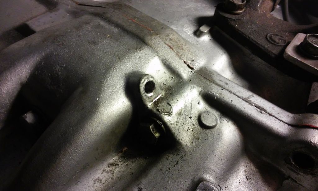
Put in some hours after work tonight, I've had some bits arrive lately and have been itching for the weekend, couldn't wait another night Tonights little job: replace that dodgy looking steel 6mm coolant barb that sticks out the top of the engine block with something more robust and modern. I sourced and purchased (at quite exorbitant cost) some 6mm stainless hose barbs with a 1/16 NPT thread and a bottoming tap, i.e tapered pipe thread for maximum water tight sealing threads Tapping drill size is 6mm or thereabouts, using the original steel pipe as a guide. Drilling it out I was left with a thin layer of steel in the engine block, pulled it out with a pair of pliers. Only used about the first 10mm of the bottoming tap, any deeper and the taper would have been to far in making the hose barb fit loosely. A nice snug fit is needed. I'm glad I did this, drilling out the old I was greeted with copious amounts of red flakes from inside the block, not good! Don't know why they used steel in the first place, silly idea.
Drilled out the old, no going back now! If you do this make extra extra sure you remove all chips and crap from inside the block before you put the barb in.
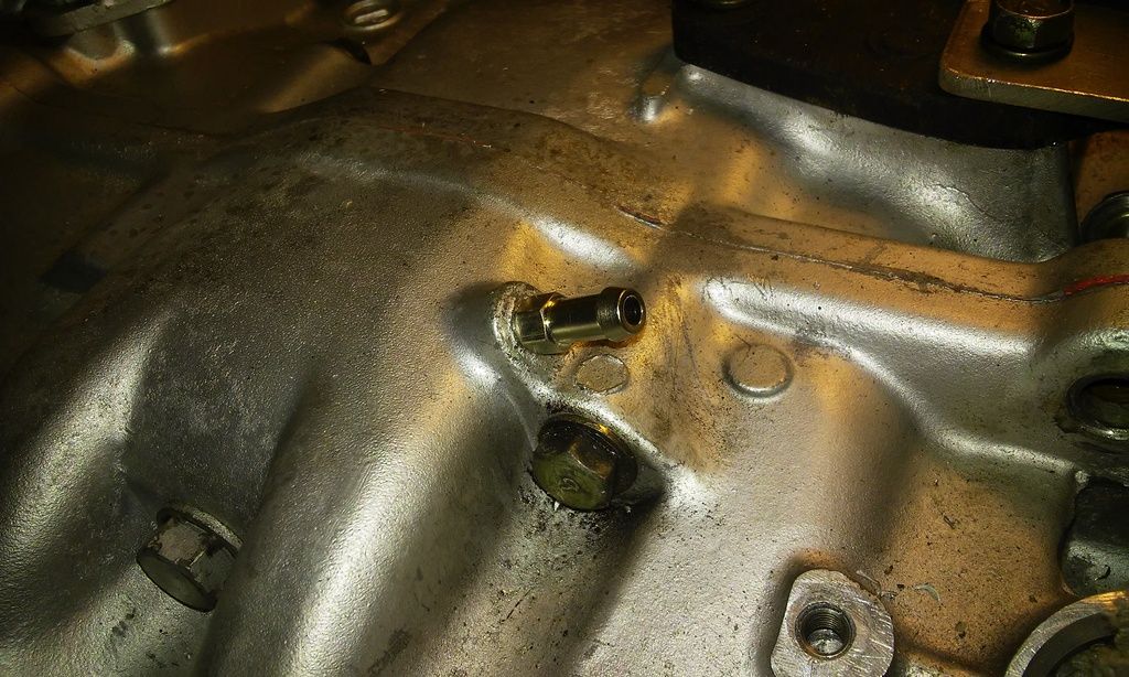
In with the new, I like the way this is looking...hey! you can also see my m6 helicoil for the old dizzy hold down bracket, now a coil pack mounting bracket
Didn't think of this when I was installing the coil pack, will be a squeeze for sure when the hose is on there
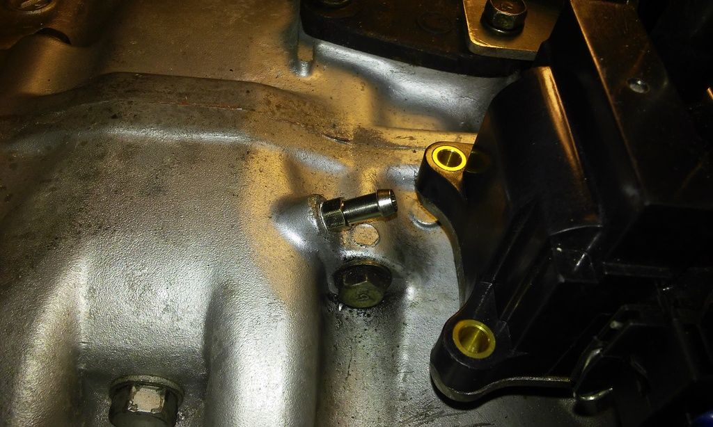
A couple of turns of teflon tape for good measure and the job is a good un' I don't care if this barb never comes out, it shouldn't have to as long as it doesn't leak. The stainless barb can seize itself in there if it wants, all the better for sealing the coolant in!
Put in some hours after work tonight, I've had some bits arrive lately and have been itching for the weekend, couldn't wait another night
Drilled out the old, no going back now! If you do this make extra extra sure you remove all chips and crap from inside the block before you put the barb in.
In with the new, I like the way this is looking...hey! you can also see my m6 helicoil for the old dizzy hold down bracket, now a coil pack mounting bracket
Didn't think of this when I was installing the coil pack, will be a squeeze for sure when the hose is on there
A couple of turns of teflon tape for good measure and the job is a good un'
Will it ever end!?
-EA81 TWIN CARB!!!!
-L series 5 speed
-Custom paint job
-2" lift
-Full custom re-wire
-L series front end
-EA81 TWIN CARB!!!!
-L series 5 speed
-Custom paint job
-2" lift
-Full custom re-wire
-L series front end