Page 1 of 1
Inverter project... help!
Posted: Tue Mar 31, 2009 1:09 pm
by ScubyRoo
Hey folks!
Ok so I have officially spent too much time trying to wire in my inverter and the bastard still won't start. Why am i screwing around with an inverter? I'm hiding it in between the centre console and the low range lever and naturally the cord doesn't reach....
Basically when I put in my stereo I found a wire that was hot in acc and on, but off when the ignition was off - perfect for my inverter. So I chopped off the cigarette socket connector, and have run auto electric cable from the hot wire to the inverter's original input cables. Problem is neither flicking the switch nor joining the cables directly has an effect on the little 'power on' light. I've used a multimeter and measured ~12v (d/c) at all connections, including at the switch. I've connected the outlet cables as they came out of the inverter and tried a few difference appliances but still no power

. I've also tried with the multimeter across the two outlet cables but can't get a reading... not sure what setting I should have it on?
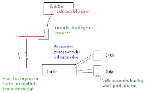
Here's the schematic diagram...
Suggestions?
Owen.
Posted: Tue Mar 31, 2009 2:05 pm
by AndrewT
note - the link to the diagram is broken...
Posted: Tue Mar 31, 2009 2:12 pm
by Alex
tried hooking it up strait to a battery? just to ensure the inverter isnt buggered.
earthing could also be a problem.
also make sure theres enough current running through your existing cable. Maybe its hooked up to something like an interior light, which isnt supplying enough current to get the inverter to power up.
just sum ideas.(make sure the fuse in your inverter isnt blown either)
alex
Posted: Tue Mar 31, 2009 2:22 pm
by ScubyRoo
image should work now... forgot to put in that it has a fuse on the positive wire about 10cm from the connection to the car...
keffa, i checked with the multimeter, full 12v flowing in at the base of the inverter... so it might as well be hooked up to the battery... it runs with as little as 10v anyway so current shouldn't be a problem.
No internal fuse on the inverter (it was in the plug) and is now inline (as mentioned above)
I think the inverter itself might be stuffed

Posted: Tue Mar 31, 2009 4:21 pm
by daza
ScubyRoo wrote:full 12v flowing in at the base of the inverter... so it might as well be hooked up to the battery...
Keeping with your water analogy, what Keffa's saying is if the hose(wire) isn't big enough, not enough water(current) will be able to flow.
The straight to battery test is worth doing to check it's still working.
Daza.

Posted: Tue Mar 31, 2009 4:42 pm
by vincentvega
picking some random wire and using it to power your inverter with no idea of its origin is not a good idea.
do the direct to battery test. if the inverter works then run a decent supply to it
Posted: Tue Mar 31, 2009 5:47 pm
by ScubyRoo
It works! Thanks for all your advice everybody!
As i said earlier, the multimeter was reading 12v from the connection at the dash all the way to the switch, so flow wasn't a problem in that sense. I'm not sure if anyone looked at the diagram carefully, as my main problem was smacking obvious and I'm annoyed I didn't see it earlier! Look carefully at the diagram and see if you can spot the problem (think year circuitry back in high school) and how I had my initial input.... see it yet????.....
I had both + and - charged from the + wire! oops! So basically there was 12v current either side of the switch, so no way to actually complete the circuit (i think...) so anyway I ripped out the 'joiner' and earthed the - onto the car frame, double checked my switch (which was wired wrong anyway...) and hey-presto! I have photos of the process for anyone else that is interested in doing something similar, I'll put em up after tea so you can see how it turned out.
Thanks again for your input fellas!
Cheers, Owen.
Posted: Tue Mar 31, 2009 5:56 pm
by Gannon
What size inverter is it? 150W 300W 600W?
You are gonna need a decent supply and some wiring from behind the dash isnt gonna cut the mustard.
If you want to have it controlled by the ignition do as follows....
* Buy some heavy duty power cable rated to your requirements
150W = 14 gauge cable
300W = 12 " "
600W = 10 " "
* Run it from the battery, through a fuse, through a heavy duty relay (horn relay or similar) and to the inverter.
* Run a wire from somewhere that comes on with acc or run, to the relay.
Using suggested size cables will reduce voltage drop and maintain a constant output voltage under varying loads
Posted: Tue Mar 31, 2009 5:56 pm
by Alex
Its still not a good idea using that power cable. Trace it backand see where its running to. Just be careful, we dont wat ya car to burn to the ground! Its been done many times before
alex
Posted: Tue Mar 31, 2009 7:07 pm
by ScubyRoo
You know it's been a long day when you carry the fuse box cover inside and wonder why it's in your hand...
I traced the wire back, oddly enough it feeds back into the interior fuse box connected to the #17 15amp fuse (radio) - the inline fuse is also 15A. The inverter is only a little one at 150W and will be used to charge phones, laptops that sort of thing... nothing that draws more than a few amps I suppose. The wiring I've used is from jaycar, to quote the catalogue it was 25 Amp DC Auto Power Cable. As I said in an earlier post, the problem hasn't been not enough power, instead it was actually incorrect wiring. All contacts were done with crimped connector plugs and covered with electrical tape.
With connecting straight to the battery, where is the best place to get cables through the firewall? I had a pretty good look but came up blank.
Posted: Wed Apr 01, 2009 7:55 am
by daza
150W of 240V output can be up to 25Amps into the inverter at 12V.
And the voltage drop in the cable means less voltage in, with means less power out.
I really think you should run it as described by Suparoo.
Daza.